Mid-range and larger p5 and i5 servers need an HMC to create and manage logical partitions, dynamically reallocate resources, invoke Capacity on Demand, utilize Service Focal Point and facilitate hardware control.
High-end servers with Bulk Power Controllers (BPC), such as the IBM System p5 model 590, p5-595 and p5-575 systems, require at least one HMC acting as a DHCP (Dynamic Host Configuration Protocol) server. Two HMCs are recommended for enhanced availability.
Mission critical solutions, even those hosted on entry or mid-range servers, may benefit from having dual HMCs.
There are many factors to be considered when planning and setting up the HMC and managed server environment. For more information, please see the IBM HMC best Practices whitepaper.
The basic setup requirements are relatively simple, however there are several key points related to the network between the HMC and Managed Server, and between the HMC and the Logical Partitions (LPARS).
The “IBM HMC best Practices whitepaper” referenced above is an informal collection of Hints & Tips intended to provide a simple worked-example. Although there are alternative setup arrangements, this example illustrates the most common environment for IBM System p, and eServer p5 systems.
Please Note that this document has not been updated since Aprli 17 2007, it should be considered as mostly covering the concepts. Please always refer to the official documentation.
Introduction
HMC attached to the Flexible Service Processor (FSP) of the Managed Server via a “private” Ethernet, and to each Logical Partition (LPAR) via an “open” Ethernet network.
Private network
“Private” network means the use of a selected range of non-routable IP-addresses. It is intended that the only devices on the HMC private network will be the HMC itself, and the Managed Servers. To be precise, the HMC is connected to the FSP (Flexible Service Processor) of the Managed Server(s).
On most System p, and eServer p5 systems, the FSP provides two ethernet ports labelled HMC1 and HMC2, allowing for the connection of 1 or 2 HMCs. However, on certain “high-end” systems (e.g. p590/595 and p575) which have a Bulk Power controller, the HMC private network connects to a small hub within the Managed Server frame.
Some systems (e.g. p590/p595) have dual-FSP, the second FSP being a “redundant” backup. It is also possible to order a redundant FSP for p570 systems. The basic setup requirements are essentially the same – the HMC must be connected to each FSP, so additional network hardware will be required (e.g. LAN switch) when there is more than 1 FSP or there are multiple Managed Servers.
Also important – each FSP port on the managed server should be connected to ONLY ONE HMC.
Open network
“Open” network means a network connection from the HMC to the Logical Partitions and, potentially, to other systems on your regular network infrastructure. If desired, the open network could also be connected to suitable Firewall/Router for connection to the Internet. Such a connection to the Internet would enable the HMC to “Call-Home” when there are any hardware errors to report.
The HMC itself provides its own Firewall (using iptables) on each of its network Interfaces. The basic firewall configuration is automatically setup when the HMC code is installed, but further configuration may be necessary.
HMC as a DHCP Server
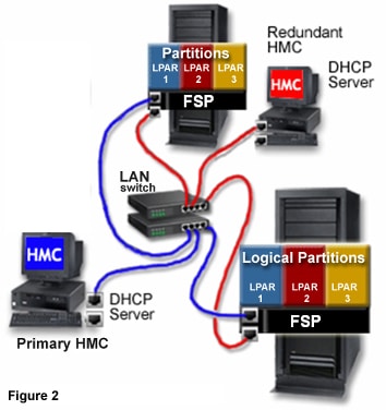
Figure 2 above shows a dual-HMC environment with two Managed Servers. The Primary HMC is connected to the first port on each FSP, and the redundant HMC is connected to the second port on each FSP. Each HMC is configured as a DHCP server, utilizing a different range of IP addresses. The connections are on separate private networks – it is important to ensure that no FSP port accidentally ends up being connected to more than one HMC.
For each Managed Server on any given network, each FSP port (which is connected to an HMC) requires a unique IP-address. The easiest way to achieve this is to make use of the HMC built-in DHCP server capability. When the FSP detects the network link as being active, it will issue a broadcast request to locate a DHCP server. When properly configured, the HMC will respond to that request by allocating one of a selected range of addresses. Subsequent requests from the same FSP will be allocated the same IP-address.
When there are multiple Managed Servers, a LAN switch will need to be provided for the HMC to FSP private network. Alternatively, this private segment could be provided as several ports in a private VLAN on a larger managed switch. With potentially multiple “private VLANS”, take care to ensure that they really are isolated – i.e. no possible cross-over traffic.
Because this is an entirely private network, the use of a HMC as a DHCP server should not have any impact on existing network infrastructure. However, there are some implications regarding LAN switches which will be described later in this document.
If DHCP is NOT used, the network configuration settings for each FSP would need to be changed from “dynamic” to “static” addressing, and a specific IP-address would need to be defined for each port. This configuration can be achieved by using the ASMI (Advanced Systems Management Interface) of the FSP. Whilst that may not be a significant amount of work with only one or two servers, it becomes a more difficult task when there are many servers attached to an HMC. Also there are several implications – for example, if an FSP needed to be replaced for some reason, the replacement FSP would be configured to use the default “dynamic” addresses, and would need to be reconfigured using ASMI before it could be attached to an HMC on a network using “static” addresses.
For a dual-HMC environment, each HMC would also be connected to the LPARs, and to each other, on the same open network.
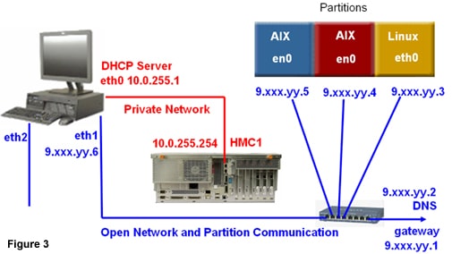
Figure 3 shows an HMC connected to a single managed server on the private network, and to three LPARs on the Open network. It is possible to order an additional Ethernet adapter for the HMC, and thus to have three (or more) network interfaces. If desired, this third network could be used as a “management” network. Or – in the case of a Cluster system – the third network would be connected to the CSM (Cluster Systems Manager) Management Server.
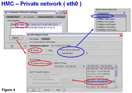
Figure 4 shows the HMC User Interface panels for configuring the Private network
In this example, I have selected the first interface (eth0) for the Private network, and enabled the HMC as a DHCP server for that network. I have also selected one of the ranges of addresses which are provided for the Private network. Note: The HMC takes the FIRST address within that range – in this example, 10.0.255.1
Adapter settings
The default for the adapter settings is “Autodetection”. Whilst this is appropriate in most cases, there are some occasions when it may be necessary to configure the required settings manually (for example, 100Mbps Full Duplex). Manual setting would be required if this adapter is connected to a LAN switch which does not produce the desired behavior for “Auto detection”. There are several methods to determine the actual port “Media Speed” one the link has become active. These will be described shortly.
Figure 5 shows the HMC User Interface panels for configuring the Open network
I have selected the second interface (eth1) for the Open network, and
also specified that this network will be used for communication to the
LPARS (“Partition communication” option). It is very unlikely that we
would want the HMC to obtain an IP-address from some other DHCP server
which is on the Open network, so I have selected the “Specify an IP
address” button, and entered the desired IP-address on the Open network.
For the Open Network, we may also wish to configure the HMC Firewall. For example, to allow remote access to the HMC using webSM (Web-based System Manager) and SSH, we would enable “WebSM” and “Secure Shell”. The currently-defined iptables (Firewall settings) are displayed in the lower panel. I have chosen to highlight a couple which are particularly important. “RMC” is used for the communication between the HMC and the LPARs (for Service Focal Point and Dynamic Reconfiguration options), and “FCS” is used for the communication between HMCs which are on the same subnet.
This panel also shows the TCP/IP ports and protocols which are used. This is very useful information if you are considering installing an additional Firewall on the open network.
From Figure 6(open network above) shows the other network setup which is required – i.e. specify a DNS server if one is available on the Open network, and specify any routing requirements. In particular, we should specify a default GATEWAY if one is available and if it is required for access from the Open network to other corporate network(s) or to the Internet.
Note: If configured to use the Internet for “Call Home” (Service Agent), that traffic will use whichever network has the default GATEWAY defined, and will attempt to use that network to reach the Internet.
HMC – identifying the network ports
Clearly, it is essential to connect the Private and Open networks to the appropriate network Interface on the HMC. These ports will be eth0 and eth1, but the physical ports (connectors) an the HMC become assigned as eth0 or eth1 depending on the hardware configuration and the type of HMC.
IBM Systems Hardware Information Center provides a description of the
possibilities, “Identifying the Ethernet port defined as eth0” at http://publib.boulder.ibm.com/infocenter/eserver/v1r3s/topic/iphai/ethernetrules.htm
After identifying the Ethernet ports from that description, a simple
test can be performed to quickly determine the correct ports. For this
test, it is only necessary to for the link to become active – therefore
an unused LAN switch could be used for this purpose. Connect an ethernet
cable between the LAN switch and one o fthe HMC Ethernet ports. Then,
using a terminal session on the HMC, run the command
tail -f /var/log/messages
Assuming that the link becomes active (indicated by lights next to the
port on the HMC, and on the LAN switch) we should see something like
this:
     Oct 30 16:55:28 daihmc kernel: bcm5700:
     eth1 NIC Link is Up, 100Mbps full duplex;
     receive & transmit flow control ON.
Which is a clear indication of the actual port that has just been selected, and also confirmation of the Media speed (in this example 100MBs full duplex). If the Media Speed result was not as expected, may need to manually configure adapter settings using the HMC User Interface panels.
Now that we have configured the Private and Open Network interfaces, and identified/confirmed the respective ports on the HMC, we can connect the Managed Server.
Connecting a managed server to an HMC
Note: the following description applies to servers excluding p590, p595 and p575
Establish an Ethernet connection between the first FSP port on the
managed server (usually labelled HMC1) and the first HMC’s private
network interface. Connect power to the managed server (if it is not
already connected).
Then, using a terminal session on the HMC, run the command
tail -f /var/log/messages | grep DHCP
Eventually, we should see something like this:
DHCPDISCOVER                    from 00:0d:60:4d:73:d8 via eth0
DHCPOFFER on    192.168.255.254 to   00:0d:60:4d:73:d8 via eth0
DHCPREQUEST for 192.168.255.254 from 00:0d:60:4d:73:d8 via eth0
DHCPACK on      192.168.255.254 to   00:0d:60:4d:73:d8 via eth0
Note: Obviously the messages will not be formated like that, I have simply re-arranged the text slightly to improve clarity.
The first message is a DHCPDISCOVER broadcast from the FSP to
determine if any DHCP server will respond, and including the MAC address
of the FSP Ethernet port (e.g. 00:0d:60:4d:73:d8).
The second message is from the HMC, DHCPOFFER – offering an IP-address (e.g. 192.168.255.254).
The third message is the response from the FSP, DHCPREQUEST – requesting to use that address.
The fourth message is the HMC, DHCPACK – acknowledging that the FSP now has that address.
Any subsequent DHCP request from the same FSP port will be re-issued the same address.
| Handy Hint | |
|
If the server already has power connected, and is at standby
state (01 N V=F shown on the operator panel), we can cause a new DHCP
request by briefly dropping the link at the FSP. If there are LAN
switches between the FSP and the HMC, remove the Ethernet cable from the
FSP itself for about 1 minute, then re-connect it. Return to HMC and
observe the output from /var/log/messages. Within a couple of minutes,
we should see the DHCP messages. Note: This tip does NOT apply to p590/p595 or p575 systems |
We can see which addresses have been issued by the HMC
lshmc -n
The last part of the output “clients=” shows the addresses which have been issued by the DHCP server.
What if we do NOT see a DHCP request?
- Check the Private network / LAN (try a direct cable if possible)
- Investigate any LAN switch settings which may prevent DHCP request
- Check the Managed Server has power connected ( op-panel shows “01”)
- disconnect Ethernet cable from FSP for approx 1 minute, then reconnect
- Determine whether FSP has been set to use static addresses
-
Reset FSP
Each of these items is described in later sections of this document.
The Hardware Server Manager (software which is running on the HMC)
“polls” the addresses which have been issued by the HMC. So, it may take
several minutes before a newly-attached server appears on the HMC in
the “Server Management” section, or as shown by the line-mode command:
lssysconn -r all
   hscroot@daihmc:~> lssysconn -r all
   resource_type=sys,type_model_serial_num=9111-520*10DE9BC,
   sp=primary,sp_phys_loc=unavailable,ipaddr=192.168.255.254,
   alt_ipaddr=unavailable,state=Connected
Connecting the HMC to the Open network
Establish an Ethernet connection from the HMC port – which has been defined as the Open network Interface – to the appropriate LAN switch. When TCP/IP is configured in any LPARS, they will attempt to contact the HMC over this network.
Confirming HMC network adapter “Media Speed”
To confirm the actual port settings (once they have been connected to a LAN switch or directly to the FSP), use the HMC “Network Topology” option as shown in Figure 7.
Service Applications / Service Focal Point / Service Utilities / Actions / View Network Topology
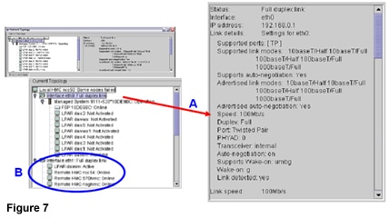
Selecting one of the HMC network Interfaces (e.g. eth0 selected at
“A”) allows us to view the media settings which were specified
(“Advertised link modes”) and the actual link setting (“Speed” /
“Duplex”)
Note: Under the Open Network Interface (shown at “B”) will be a list
of LPARS which are currently connected, and other HMCs which have been
automatically discovered on the same Open subnet.
Secure connection from HMC to FSP
The FSP has several “userids” defined, including: HMC; admin and general.
For a new machine (or one which has been reset to “Factory
Configuration”), a password must be set for each of those userids. The
HMC will use the userid “HMC” and the password which you have set, in
order to establish a secure (SSL) connection to the FSP.
A new machine attached to the HMC will appear first as an IP-address, with the message “Pending Authentication”, as shown in Figure 8. Right-click the IP-address, and select “Update Managed System Password”.
The HMC wizard will prompt for passwords to be SET for the userids “HMC”; “admin”; and “general”. The passwords will be set in the FSP itself. The “admin” and “general” userids can then be used to login to the FSP using the ASMI interface. Clearly it is important to keep a safe record of the passwords which have been set.
Connecting managed servers to an HMC via a private network

For more information, please see Reliable communication between the HMC and managed p5/p6 servers.
FSP set to use static IP address
If the FSP had been previously configured to use a static address, it will not issue a DHCP request when connected to an HMC. The ASMI interface may be used to connect to the FSP and check/set the network configuration. If using web browser to access ASMI, obviously we need to know the current IP address of the FSP port. The Operator panel (function “30”) may be used to display the current IP address of each of the FSP ports.
Login to FSP using ASMI
The userid “admin” has the default password “admin”. However, the password may have been changed (either after attachment to an HMC or through the ASMI interface). If the admin password is NOT known, place a hardware call and request a temporary celogin password. The password for celogin is generated for a specific machine serial number and a specific date. Once logged-in as celogin, the password for the admin and general users can be reset.
The celogin password is considered IBM Confidential. It can only be used by IBM employees. If hardware support of the managed server has lapsed, IBM will charge a fee to use the celogin password.
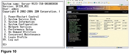
Figure 10 shows examples of the ASMI interface. (Note: ASCII termnal connection is not possible on p570/p590/p595 systems). If the managed Server is already attached to an HMC, the ASMI interface is available through Service Applications / Service Utilities.
Setting FSP Network Configuration using ASMI
Figure 11 shows the network configuration settings using ASMI through a Web-browser (the panels are similar when using ASCII terminal connection)
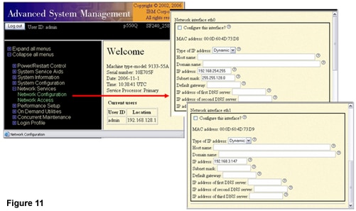
When attached to an HMC which is setup as a DHCP server, the “Type of IP Address” should be set to “Dynamic”.
Note: The above information was snagged from here. The developerworks sites are being sunset. Thus, copied here for archival purposes, in case developerworks is no longer accessible.


